Every robot arm on the market has a spec sheet, and every spec sheet is written by the people trying to sell you the arm. That doesn’t make them dishonest. It does mean the numbers are chosen to show the machine at its best, and the qualifications that matter are usually a footnote.
Here’s what the four headline figures actually mean, and where each one quietly stops being true.
Payload is not the weight of your part
Payload is the mass the arm can carry at the tool flange. That’s the mounting face at the end of the wrist — not the part you want to move.
Everything between that flange and your workpiece comes out of the budget first:
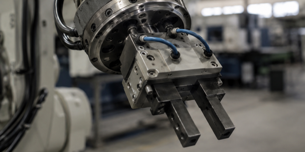
- The gripper or end effector, which on a two-finger pneumatic unit is rarely trivial
- Any tool changer, force sensor or camera mounted at the wrist
- Cabling and air lines routed to the tool
- The workpiece itself
A published payload also assumes the load’s centre of gravity sits close to the flange. Hang the same mass further out on a long gripper and the moment the joint has to hold rises with it. Manufacturers publish payload-versus-offset diagrams for exactly this reason, and those diagrams are the number you should be designing against.
If you are within ten per cent of the rated payload on paper, you are over it in practice.
Reach is measured from somewhere specific
Maximum reach is the distance from the centre of the first rotational axis to the tool flange with the arm extended. Two things follow from that definition.
First, it’s measured from a point inside the robot, not from the edge of its base. The footprint you have to allow for on the floor plan is bigger than the reach figure suggests.
Second, and more importantly, an arm at full extension is at its weakest and least precise. Joints near their limits have less torque available, and small angular errors translate into larger positional ones the further out you go. The working envelope you can actually use is smaller than the sphere the datasheet draws.
There’s also usually a dead zone directly above and behind the base that the arm physically cannot reach into. If your fixture sits there, the reach number told you nothing useful.
Repeatability is not accuracy
This is the most misread figure on any robotics spec sheet, and the difference is not academic.
Repeatability is how closely the arm returns to a position it has already been to. Send it to the same taught point a thousand times and repeatability describes the spread of where it actually lands.
Accuracy is how closely the arm reaches a position it has been told about in coordinates but never physically taught — how well its internal model of itself matches reality.
Almost every manufacturer publishes repeatability. Far fewer publish accuracy, because accuracy is typically an order of magnitude worse.
Which one you need depends entirely on how you program the cell:
- Teaching points by hand — repeatability is the number that matters
- Generating paths offline from CAD — accuracy is the number that matters, and you will probably need to calibrate the specific arm you receive
- Working from vision — you need both, plus the calibration between the camera frame and the robot frame, which is its own project
Cycle time figures come from a best case
Published cycle times and maximum joint speeds are measured under conditions chosen to produce a good number: a light or nominal load, an unobstructed path, no waiting on anything else in the cell.
Your cycle will be slower, and usually not because of the robot. It’ll be slower because the arm is waiting for a fixture to clamp, a machine door to open, a vision system to return a result, or a conveyor to index. In most cells the robot is not the bottleneck — which is worth knowing before you pay for a faster one.
What the sheet says, and what to ask
| Published figure | What it leaves out | What to ask |
|---|---|---|
| Payload | Tooling, cabling and centre-of-gravity offset | What’s the payload at my actual tool offset? |
| Reach | Measured from inside the base; envelope has dead zones | Can I have the working envelope drawing? |
| Repeatability | Says nothing about absolute accuracy | Is accuracy published, and is calibration available? |
| Cycle time | Best-case load and path, no cell interlocks | What load and path was this measured with? |
| Protection rating | Often differs between the wrist and the body | What’s the rating on each part of the arm? |
| Mounting | Ceiling and wall mounting can change rated payload | Are the figures the same in my mounting orientation? |
Three questions before you order anything
What is the total mass at the flange, including everything? Add up the gripper, the sensors, the cabling and the heaviest workpiece. Then check that total against the payload-versus-offset chart at the distance your tool actually puts it.
Where does the arm need to reach, and from what mounting position? Sketch the envelope over your cell layout rather than trusting the headline figure. Include the dead zone.
How will the cell be programmed? If the answer is offline or from CAD, you need to be reading accuracy figures, not repeatability figures — and you should be asking about calibration before you buy, not after.
None of this requires a sales call. It requires the full specification in front of you, which is why we publish it on every listing.