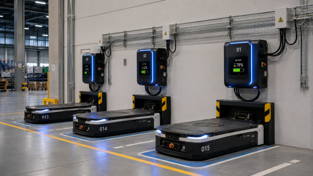
You commission a fleet of AGVs, everything works in testing, and then six weeks into production your utilization numbers start slipping. Throughput drops during second shift. You dig into the logs and realize your vehicles are queuing at the charger. One station, six robots, and nobody planned the math.
I’ve watched this play out more times than I’d like. Charging infrastructure is treated like an afterthought , something to sort out after the vehicles arrive. It isn’t an afterthought. It’s the constraint that quietly governs everything your fleet can do. Get it wrong and your automation ROI gets quietly strangled. This guide covers how to actually design AGV charging stations from the ground up: station types, placement logic, fleet math, and the integration details that don’t show up in vendor brochures.
Understanding AGV Charging Architectures
Before you specify anything, you need to know which charging architecture fits your operation. There are three real options: opportunity charging, autonomous docking charging, and manual plug-in charging.
Manual plug-in is exactly what it sounds like , someone walks over and connects a cable. It survives in small, slow-moving fleets where a vehicle runs one shift and charges overnight. If you’re running two or three shifts with any meaningful volume, manual plug-in is a bottleneck waiting to happen. Don’t spec it for serious automation.
Autonomous docking stations use a physical contact plate or inductive pad built into the floor or a wall mount. The AGV drives into position, aligns within a tolerance (typically ±10–15 mm), and charging begins automatically with no human involvement. These are the default for mid-to-large fleets.
Opportunity charging is the architecture that actually changes your fleet math. Instead of taking a vehicle offline for a full charge cycle, you design short charging windows , 5 to 12 minutes , into the vehicle’s route whenever it’s near a station. The goal is to keep the state of charge (SOC) above a working floor, usually 40–60%, rather than letting it drop to near-zero and doing a full recovery charge. Done right, opportunity charging lets you run smaller fleets with higher utilization. Done wrong , with chargers in awkward locations or insufficient station count , it creates traffic jams mid-cycle.
The first time I saw this spec wrong was at a distribution center running six MiR200s with a single wall-mount charger tucked in a corner behind the inbound dock. Vehicles were queuing 20–30 minutes just to get a charge slot. The fix required adding two more stations and moving one to a central aisle position.
Sizing Your Charging Station Count
This is where most fleet designs go soft. Vendors will give you a rule-of-thumb number. Rules of thumb are for napkins, not production floors.
Here’s the actual math. You need three numbers: cycle time (how long one full task cycle takes), charge time (how long the vehicle needs at a station to restore usable charge), and fleet size.
If a vehicle runs a 12-minute task cycle and needs 8 minutes of opportunity charging per hour, it will need roughly one charging slot every 60 minutes for 8 minutes. With six vehicles, that’s 48 vehicle-minutes per hour of charger demand. A single station that can only service one vehicle at a time provides 60 station-minutes per hour. On paper, one station covers it. In practice, that assumes perfectly spaced arrivals, zero dwell, and no variance in cycle time , none of which exist on a real floor.
Apply a utilization buffer of 1.3 to 1.5x. Round up. A fleet of six AGVs with the numbers above needs two stations minimum, three if your cycle has any clustering (shift starts, break-time surges, inbound delivery windows where everything moves at once).
For lithium-ion battery systems, which most modern AGVs run, charge rates typically range from 1C to 2C depending on chemistry and thermal limits. A 24V/100Ah pack might accept a 40A fast charge , restoring 40Ah in an hour , but many OEMs limit fast-charge cycles to protect cycle life. Check your battery spec sheet. Some platforms, like the Linde L-MATIC or Geek+ P800, publish charge curve data. Use it.
Station Placement and Traffic Design
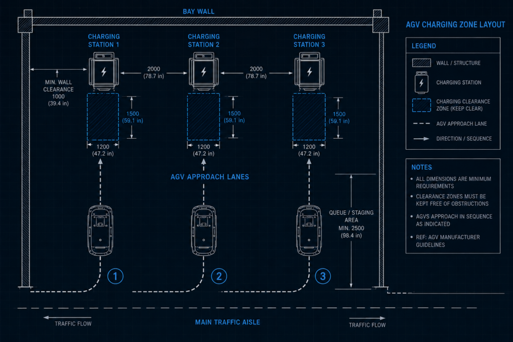
Where you put the chargers matters as much as how many you put in. A charging station placed at a dead-end creates a single point of failure. A vehicle that loses communication mid-charge, or sits longer than expected due to a fault, blocks every vehicle behind it.
Placement principles that hold up in practice:
- Position stations on loop routes, not spur routes. Every vehicle should be able to approach and depart without reversing or waiting for another vehicle to clear.
- Locate stations near high-frequency return points , staging areas, dispatch queues, end-of-line buffers. Vehicles naturally dwell here, making it low-cost to absorb a charging window.
- Allow at minimum 1.5x the vehicle footprint as clearance on either side of the docking approach lane. AGVs aren’t precision surgical instruments. They drift. Tight approaches cause repeated docking failures.
- Keep stations away from high-pedestrian zones. A parked AGV at a charger during a busy shift creates a collision risk that your safety assessment needs to account for. ISO 3691-4 covers driverless industrial truck safety requirements and includes guidance on exclusion zones around stationary vehicles , worth reading before you finalize layout. You can find the standard at ISO.org.
I spent weeks debugging intermittent docking failures at one site before realizing the floor had a 0.8% cross-slope leading into the contact plate. The AGV’s suspension was just enough to lift one contact wheel off the plate. A 10mm shim under one side of the station mounting bracket fixed it.
Power Infrastructure and Electrical Requirements
Charging stations don’t run on intent. They need real electrical infrastructure, and this is where facilities teams and automation teams frequently miscommunicate.
A typical 24V autonomous charging station for a mid-duty AGV draws 2–5 kW per station. For a 48V heavy-duty AGV , something in the tow capacity of a Toyota 8-Series or Dematic tow tractor class , charger draw can reach 10–15 kW per station. Multiply by station count, add 20% for demand headroom, and give that number to your electrical engineer before you pour concrete or mount conduit.
Charging station types by connector/interface:
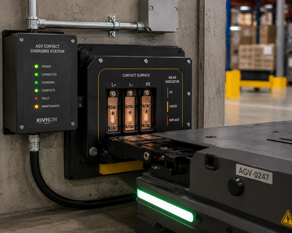
- Contact pad (floor or wall) , most common for autonomous docking, requires surface cleaning maintenance
- Inductive (wireless) , no physical contact, tolerates larger alignment variance, higher install cost, ~85–93% transfer efficiency versus ~95%+ for contact systems
- Pantograph-style overhead , common in heavy AGV and AGC (automated guided cart) applications, rarely seen in lighter warehouse robots
Most AGV OEMs will specify a preferred or required charger manufacturer. KUKA, for example, ties certain AGV platforms to specific KUKA SmartCharge infrastructure. Ignite autonomy from that spec and you’ll void your warranty before your first preventive maintenance cycle.
Pay attention to communication protocol between the charger and fleet management software. Your FMS (fleet management system) needs to know when a vehicle is charging, at what SOC, and when it’s available. This typically runs over the same Wi-Fi or MQTT-based channel as the rest of your AGV communications. Poorly integrated chargers that the FMS can’t see will cause the fleet controller to dispatch a vehicle that’s mid-charge, interrupting the cycle and potentially damaging battery chemistry over time.
Fleet Management Software Integration
A charging station that isn’t visible to your fleet management software is just a parking spot. Integration is where charging infrastructure stops being hardware and starts being a system.
Your FMS needs to manage three things: dispatch priority (when to interrupt a task and send a vehicle to charge), station allocation (which vehicle goes to which charger), and recovery logic (what happens when a charge cycle fails or a station faults).
Most modern FMS platforms , MiR Fleet, Geek+ RCS, Fetch Robotics Cloud , handle this natively if you’re running their hardware. The problems start when you’re running mixed fleets or third-party AGVs integrated against a non-native FMS.
For mixed fleets, the standard to know is VDA 5050. It’s an open interface specification for AGV/AMR fleet communication that allows different vehicles from different manufacturers to communicate with a single fleet controller. The VDA 5050 specification is maintained by the German Association of the Automotive Industry and freely available , worth reading if you’re building any kind of heterogeneous fleet. Full documentation is available at vda.de.
Set SOC dispatch thresholds deliberately. A threshold of 20% sounds conservative but may not be if a vehicle is mid-cycle and the nearest charger is 300 meters away with two other vehicles queued. I’ve seen fleets configured with 30% thresholds as the floor and opportunity charging windows triggered any time SOC drops below 70% and a vehicle is within 50 meters of a station. That configuration ran cleanly across three shifts with no unplanned charge interruptions.
Maintenance, Wear, and Operational Realities
Contact-based charging systems wear out. The copper or silver-alloy contact pads on both the station and the vehicle accumulate oxidation, debris, and mechanical wear from repeated docking cycles. A fleet running 200 charge cycles per day across a 5-station setup will typically need contact pad inspection every 3–6 months depending on environment. Dusty environments (wood processing, food manufacturing with flour or starch particulate) accelerate this dramatically.
Build a PM schedule into your maintenance calendar before your fleet goes live, not after you start seeing failed docking events. Add a monthly resistance check across contact points , most manufacturers spec an acceptable contact resistance below 10 milliohms. Above that, charge efficiency drops and you start seeing incomplete charge cycles without fault codes.
Also account for software-side maintenance. Charge logs should be retained and analyzed. A vehicle that’s consistently failing to hit target SOC by end of charge window is showing you early battery degradation. Catching it at 80% capacity versus 60% is the difference between a planned swap and an emergency replacement that takes a robot offline mid-shift.
Key Takeaways
- Design charging infrastructure before the fleet arrives , station count, placement, and electrical load need to be finalized during facility planning, not after go-live.
- Use opportunity charging for multi-shift operations , keeping SOC above 40–60% is more efficient than full-cycle charging and reduces battery degradation.
- Size station count with a 1.3–1.5x utilization buffer , perfect arrival spacing doesn’t exist on real production floors.
- Place stations on loop routes with proper approach clearance , dead-end charger positions create traffic bottlenecks and docking failure risks.
- Integrate charging visibility into your FMS from day one , unmanaged chargers produce dispatch conflicts and long-term battery damage.
Frequently Asked Questions
How many AGV charging stations do I need for a fleet of 10 vehicles? It depends on your cycle time, charge time, and shift structure, but a practical starting point for a 10-vehicle fleet running opportunity charging is 3–4 stations. Apply a 1.3–1.5x utilization buffer to your calculated demand and always round up. More stations cost less than downtime.
What’s the difference between opportunity charging and overnight charging for AGVs? Overnight charging takes a vehicle fully offline for a complete charge cycle , practical for single-shift operations. Opportunity charging restores partial charge in 5–15 minute windows during natural route pauses, keeping vehicles in circulation continuously. Most multi-shift and 24/7 operations need opportunity charging to hit utilization targets.
Can I use inductive wireless charging for AGVs instead of contact pads? Yes, and it works well for environments where contact wear or contamination is a concern. The tradeoff is lower transfer efficiency (typically 85–93% vs. 95%+), higher installation cost, and larger station footprint. For most standard warehouse applications, contact-pad charging is more cost-effective.
What communication protocol do AGV chargers use with fleet management software? Most OEM-native systems use proprietary protocols over Wi-Fi or wired Ethernet. For mixed or multi-vendor fleets, VDA 5050 is the open standard that enables a single FMS to manage vehicles and charging states across manufacturers. Confirm charger-to-FMS communication is part of your integration spec before purchase.
Building a Charging Infrastructure That Runs the Whole Shift
Charging is infrastructure, not an accessory. The fleet math, the placement logic, the electrical planning, the FMS integration , none of it is optional if you want consistent throughput across all three shifts.
If you’re still in the selection phase, the factoryrobots.net shop has AGV platforms with full specs listed, including battery capacity and supported charge architectures, so you can match vehicles to your charging design rather than retrofitting the other way around. And if you’ve already got vehicles selected and you’re working through integration specifics, reach out to the engineering support team at factoryrobots.net , they’ve worked through this problem on real floors, not just in theory.